
Transient Nozzle Simulation (Fluent)
February 8, 2026
After establishing the thermal design with regenerative and film cooling, the next step is to validate the nozzle flow behavior under realistic operating conditions by transient CFD simulation.
During ignition, the nozzle experiences rapid pressure and temperature changes. Shock waves form and propagate, and the flow takes finite time to establish steady supersonic expansion. These transients determine whether the nozzle will experience flow separation or overexpansion during start-up. Our initial nozzle calculations were theoretical values, and we were unsure whether the actual nozzle profile would function correctly.
Mesh Generation
In this section, we aim for a sufficiently fine mesh for accurate simulation without incurring excessive performance overhead. We used a 1mm mesh for the nozzle and a 2mm mesh for the environment. We also applied inflation layers at wall boundaries to create a gradual mesh refinement perpendicular to the wall surface. This produces a smooth transition from fine near-wall cells to coarser bulk elements, which is essential for accurately resolving the viscous sublayer and buffer region of the turbulent boundary layers.
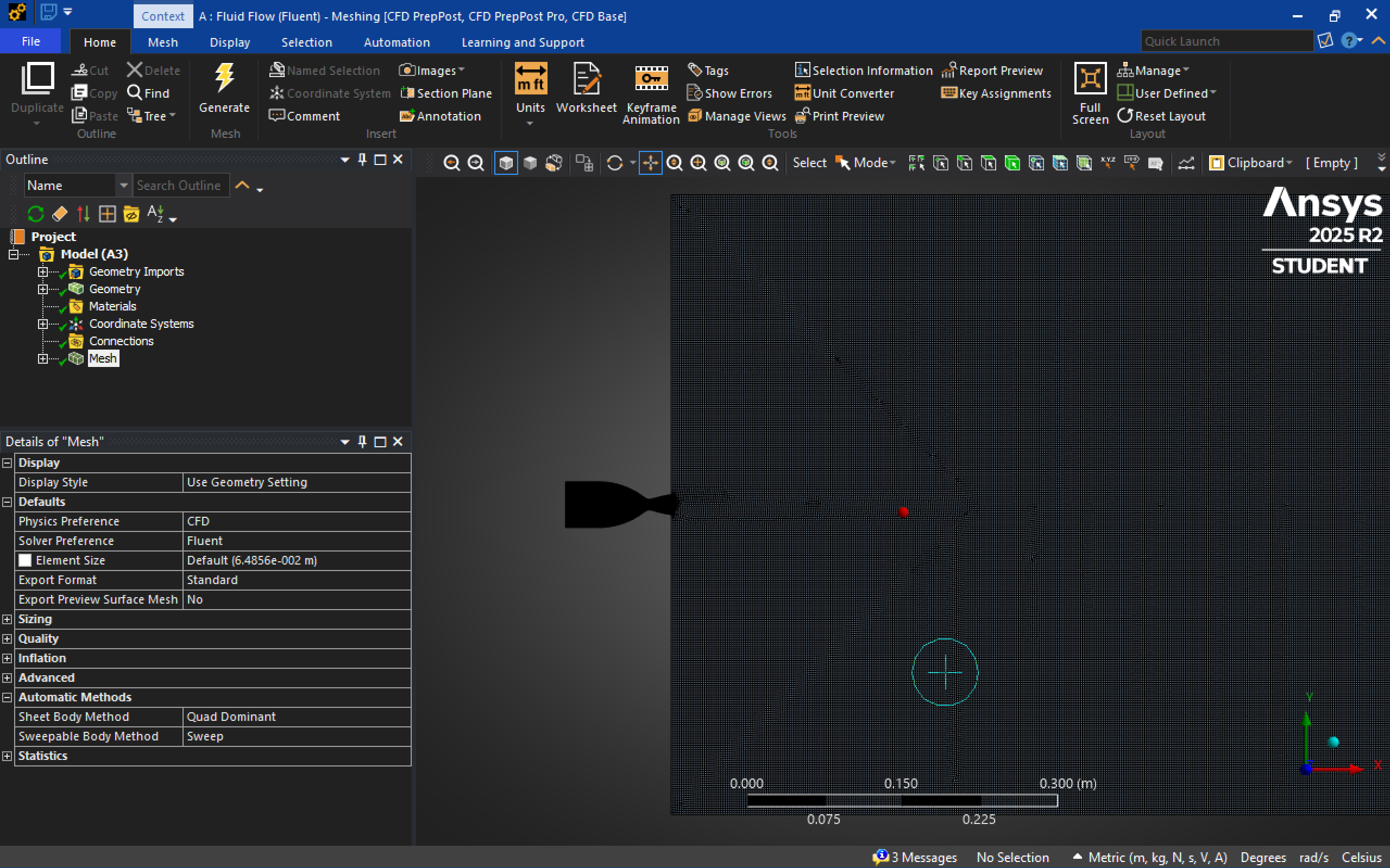
The mesh extends into the ambient domain to capture plume expansion and shock interaction with the surrounding atmosphere.
Transient Run Setup
The simulation uses a density-based transient solver, which is specifically designed for compressible flow problems where density varies significantly (such as supersonic nozzle flow). The transient formulation captures time-accurate evolution of the flow field from ignition to steady-state operation.
Solver configuration:
- Solver type: Density-based, transient
- Precision: Double-precision floating-point arithmetic
- Energy equation: Enabled to capture temperature variations and compressibility effects
- Viscous model: k-ε (2-equation) Realizable with scalable wall functions
- The Realizable k-ε model provides better performance for flows with strong streamline curvature, vortices, and rotation compared to standard k-ε
- Scalable wall functions prevent mesh-induced errors when the first cell height falls outside the ideal $y^+$ range
The simulation tracks how the flow field evolves from the initial ambient state to fully developed supersonic expansion.
Transient Flow Evolution
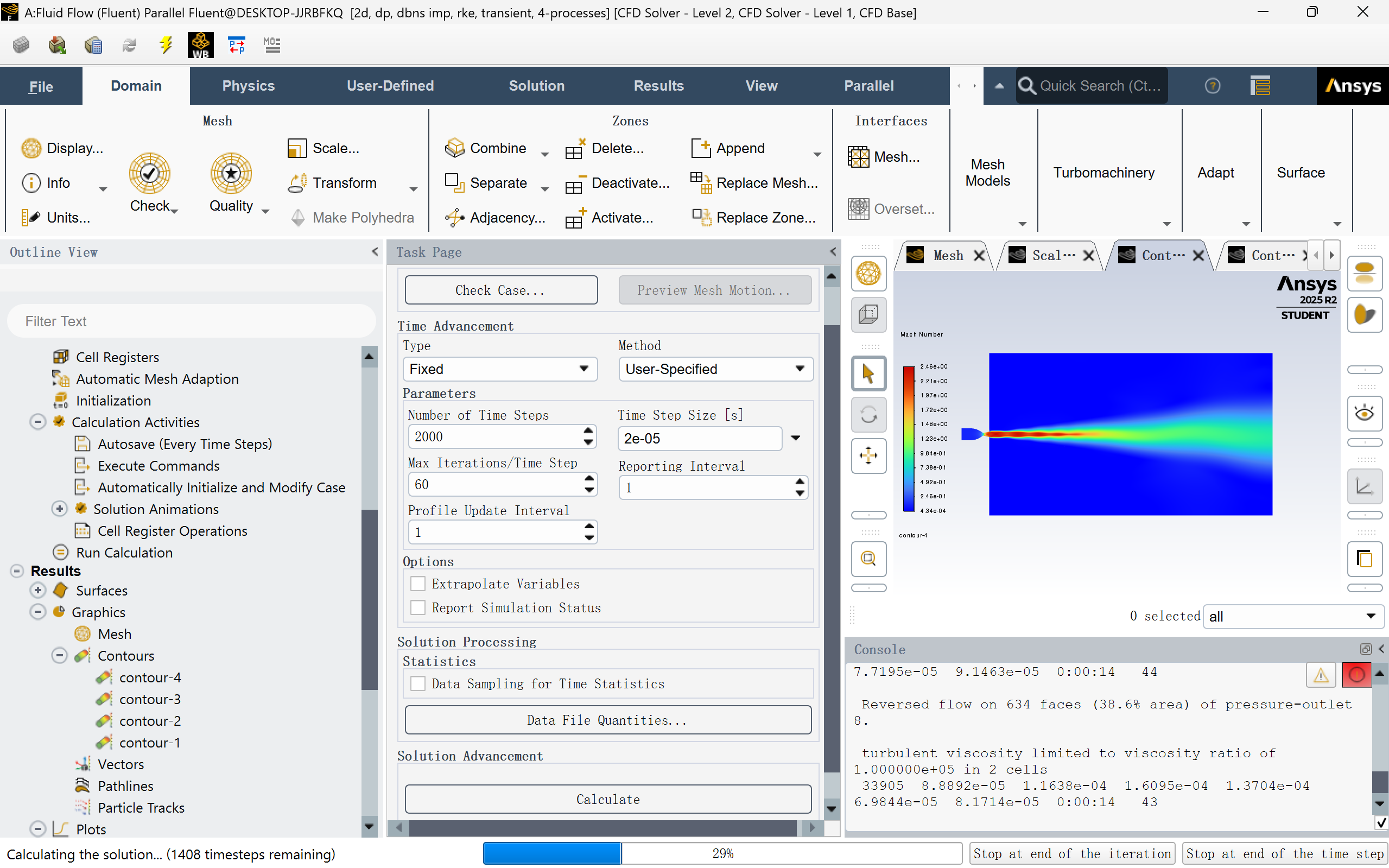
The video below shows the transient development of the flow field, from ignition to steady-state operation. Watch how the shock structure forms, how the plume expands into the ambient atmosphere, and how flow patterns stabilize.
Several key features in the video reveal the nozzle’s performance characteristics:
Near-ideal expansion: The exhaust flow at the nozzle exit exhibits slight outward divergence, but the angle is minimal. This indicates that the expansion ratio is very close to ideal for the operating conditions, with only minor underexpansion. This part could also be explained as the visual effect of the clipping layer. The near-parallel streamlines minimize expansion losses and confirm the nozzle contour design is well-optimized.
Laval nozzle: The flow accelerates smoothly from subsonic chamber conditions through Mach 1.0 at the throat to Mach 2.46 at the exit.
Shear layer mixing: Between the high-speed core flow (red) and the ambient atmosphere, an orange-yellow shear layer develops. This is turbulent mixing driven by the velocity gradient between the supersonic exhaust and stationary air. Energy dissipates through viscous shear and turbulent eddies at this interface.
Far-field deceleration: In the right-side far field, the plume expands and decelerates (transitioning from yellow to green). According to momentum conservation, as the exhaust entrains more atmospheric mass, the bulk velocity decreases:
$$\dot{m}_e v_e = (\dot{m}_e + \dot{m}_a) v_f$$
where $\dot{m}_e$ is exhaust mass flow, $v_e$ is exit velocity, $\dot{m}_a$ is entrained atmospheric mass flow, and $v_f$ is far-field velocity.
The outermost diffusion region represents turbulent dissipation, where kinetic energy is progressively lost to viscous heating and eventually disperses into the ambient environment.
Vector Field Analysis
The following plots show instantaneous vector fields for key flow quantities during steady-state operation. Vector arrows indicate local flow direction and magnitude, revealing the detailed structure of the supersonic expansion.
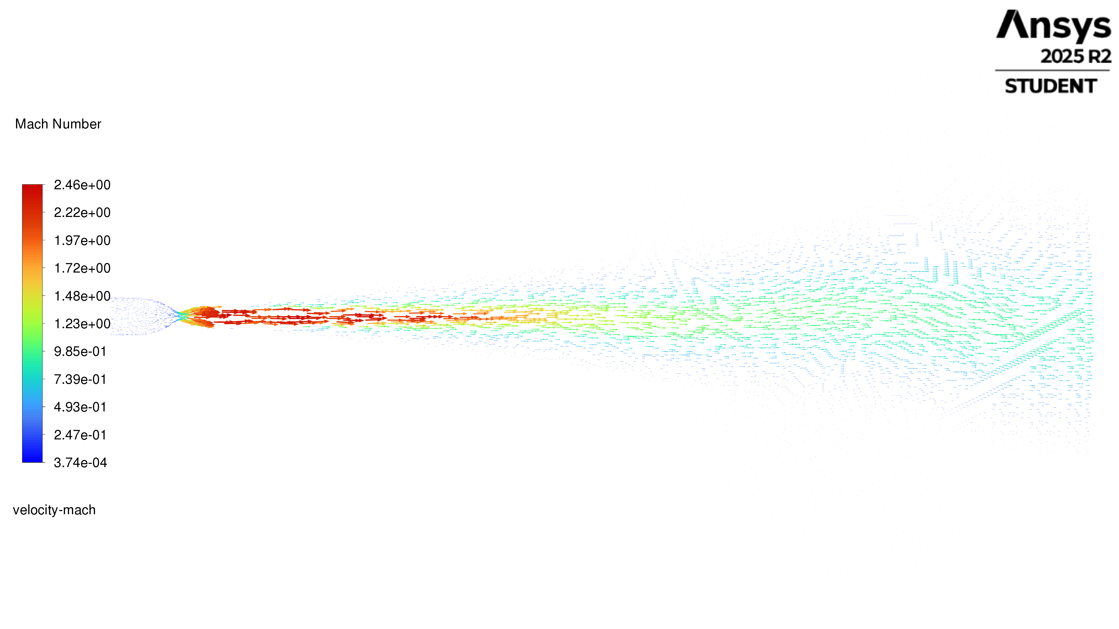
The core section of the wake ends at about 0.5m, and the wake extends to more than 1m.
The Mach field shows the transition from subsonic combustion chamber flow to supersonic nozzle flow (Ma > 2.5 at exit). The throat region clearly shows the sonic transition (Ma ≈ 1.0), and the expansion section exhibits smooth supersonic acceleration without separation. Based on this result, we are able to confirm that $A_c/A_t$ is sufficiently large to avoid chamber velocity effects, and $A_t/A_e$ achieved the design goals.
These results close the loop on the aerothermal design. Next, we will complete the initial model production for version 1.1.