
Contraction Ratio Study
January 14, 2026
While L* defines the characteristic residence time, the contraction ratio $A_c/A_t$ (chamber area to throat area) fundamentally shapes the combustion chamber’s physical dimensions. This dimensionless parameter determines the diameter of the combustion chamber relative to the throat, and in some ways may be more important than L*.
Chamber length is determined by:
$$L_c = \frac{L^*}{A_c/A_t}$$
Therefore, for a fixed L* (which we’ve established should be around 1.0-1.2m for our small engine), the contraction ratio directly controls chamber length.
From the textbooks
Classical rocket propulsion literature, particularly Sutton & Biblarz’s Rocket Propulsion Elements, provides comprehensive guidance on contraction ratios. From their 8th edition:
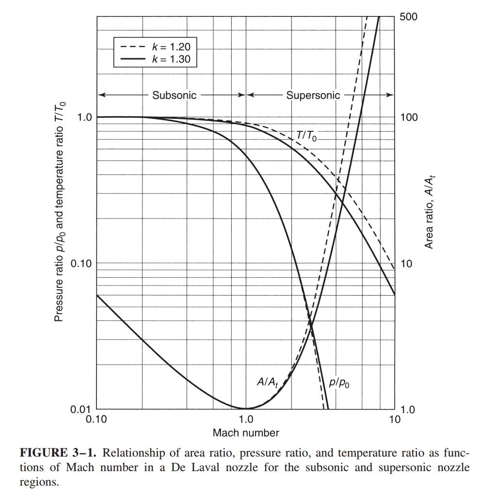
“As can be seen from Fig. 3–1, for subsonic flow the chamber contraction ratio $A_1/A_t$ can be small, with values of 3 to 6, and the passage is convergent. There is no noticeable effect from variations of k.” (p. 52)
This establishes that contraction ratios of 3-6 are thermodynamically acceptable for maintaining subsonic chamber flow. However, Sutton continues with an important caveat:
“When the chamber has a cross section that is larger than about four times the throat area ($A_1/A_t > 4$), the chamber velocity $v_1$ can be neglected… However, vehicle space or weight constraints often require smaller thrust chamber areas for liquid propellant engines… Then $v_1$ can no longer be neglected as a contribution to the performance.” (p. 75)
And critically:
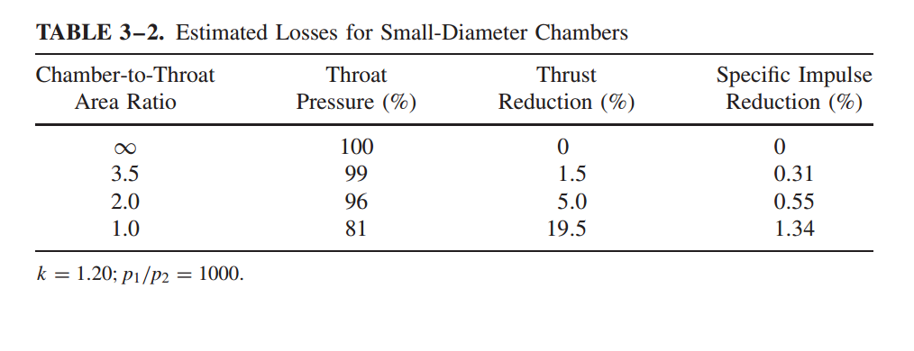
“Small chamber or port area cross sections relative to the throat area or low nozzle contraction ratios $A_1/A_t$ cause pressure losses in the chamber and reduce the thrust and exhaust velocity slightly.” (p. 86)
The Hidden Assumption
$A_c/A_t \approx 3-6$ represent thermodynamic acceptability, not optimality. They define the lower bound where subsonic flow can still be maintained without catastrophic performance loss. But “acceptable” doesn’t mean “recommended,” especially for small engines. Clearly, these guidelines were developed primarily for large engines where:
- Manufacturing tolerances are loose relative to absolute dimensions
- Heat flux densities are manageable due to favorable surface-area-to-volume scaling
- Chamber velocities remain negligible even at moderate contraction ratios
- Injector elements can be made arbitrarily small relative to chamber diameter
- You don’t want excessive compression to cause a loss of thrust.
Small engines violate every single one of these assumptions.
Is this true? Let’s verify the results directly using our KRA software.
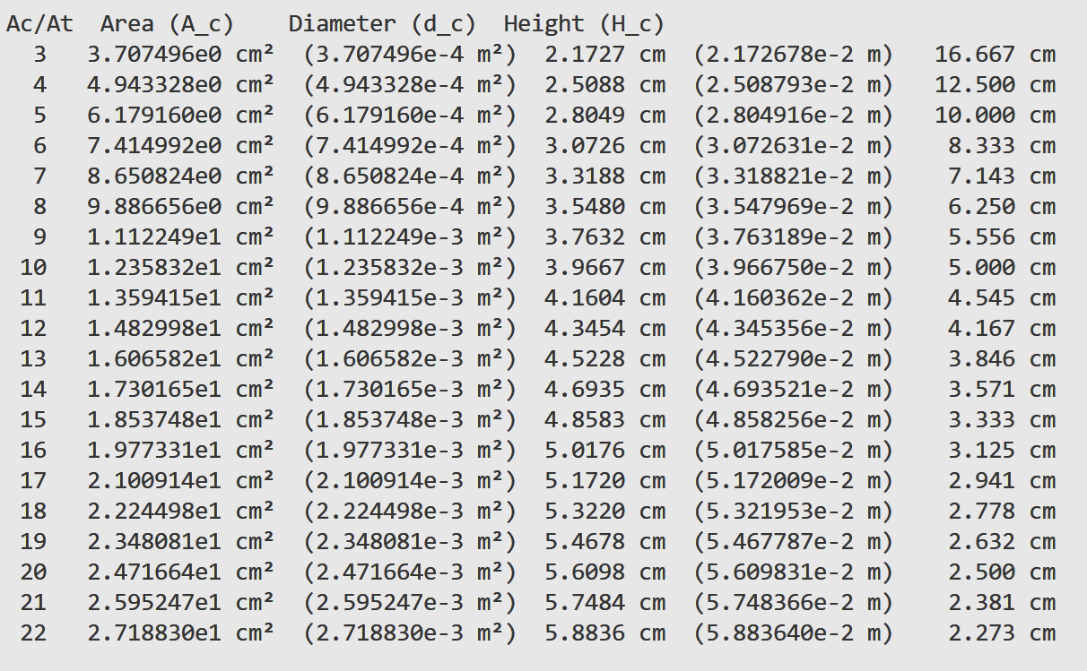
First sweep below used $L^* = 0.5$ m.
Now here is the 2nd sweep with $L^* = 1.0$ m:
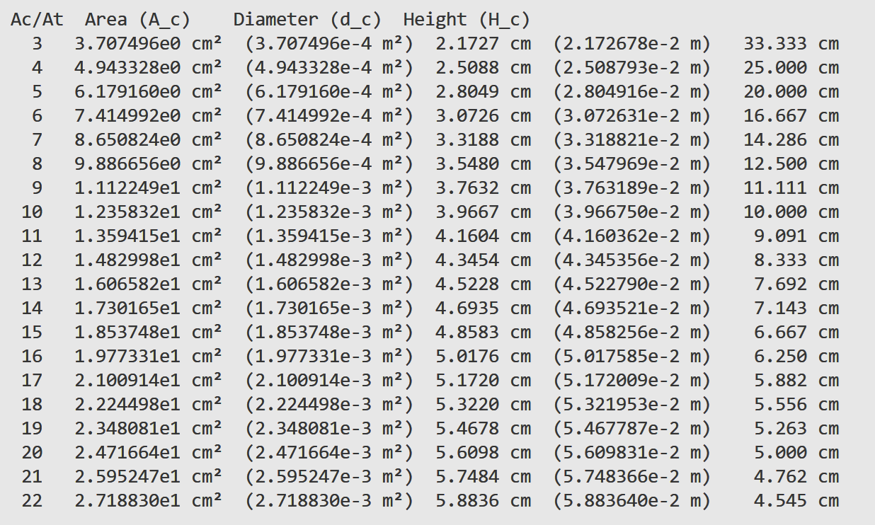
The trend is the same in both plots: lower $A_c/A_t$ makes the chamber long and narrow, while higher $A_c/A_t$ shortens the chamber and increases diameter. The only difference is that doubling $L^*$ roughly doubles the chamber length across the board.
From the $L^* = 1.0$ m sweep, the “textbook” low-contraction range looks like this:
- $A_c/A_t = 3$: $d_c = 2.17$ cm, $H_c = 33.33$ cm
- $A_c/A_t = 4$: $d_c = 2.51$ cm, $H_c = 25.00$ cm
These proportions already start to look like a tube rather than an engine.
Why this doesn’t work for small engines:
Take $A_c/A_t = 15$ from the same $L^* = 1.0$ m sweep:
- $A_c/A_t = 15$: $d_c = 4.86$ cm, $H_c = 6.67$ cm
This looks extreme at first glance, but it solves several small-engine problems at once. The larger diameter increases internal surface area, which eases regenerative cooling pressure requirements and allows practical channel sizes. The alternative is a smaller diameter chamber, which creates two hard constraints:
-
Injector packing: the chamber face gets too small to fit enough injector elements at a reasonable orifice diameter. Injector orifices cannot scale down arbitrarily (below ~0.5-0.8mm, surface tension and manufacturing limits dominate), which effectively sets a minimum chamber diameter independent of throat size.
-
Heat flux concentration: smaller diameters push wall heat flux higher, and higher $A_c/A_t$ concentrates heat flux near the throat. A simple scaling shows why. With $A_c = (A_c/A_t) A_t$ and
$$D_c = \sqrt{\frac{4 A_c}{\pi}} = \sqrt{\frac{4 (A_c/A_t) A_t}{\pi}}$$
the heat flux trend can be approximated as
$$q’’_{chamber} \propto D_c^{-0.2}$$
and the throat region scales roughly as
$$q’’_{throat} \propto \dot{m} \cdot \left(\frac{A_c}{A_t}\right)^{0.8}$$
So reducing $D_c$ drives $q’’$ upward and forces thinner walls, smaller channels, and higher coolant pressure. In other words, the chamber becomes harder to cool and harder to manufacture at exactly the scale where we have the least margin.
Sutton’s condition for neglecting chamber velocity ($A_c/A_t > 4$) assumes the chamber flow Mach number remains very low. But in small engines with tight packaging, the chamber velocity contributes significantly to the energy balance. The pressure loss scales as:
$$\Delta p_c \propto v_1^2 \propto \left(\frac{A_t}{A_c}\right)^2 = \frac{1}{(A_c/A_t)^2}$$
At $A_c/A_t = 3$, this loss is nearly 3× higher than at $A_c/A_t = 6$. These losses directly reduce $c^*$ efficiency and thrust, which is the very performance penalties Sutton warns about.
Successful Examples of Small Engines in the Real-World
It is interesting. Successful small liquid rocket engines consistently use contraction ratios well above the “textbook minimum”.
Rutherford Engine (Rocket Lab Electron, 25 kN thrust):
- Contraction ratio: ~12-15
- Chamber diameter: Relatively large compared to throat
- Enables 3D-printed chamber with internal cooling channels
RD-107/RD-108 Vernier Engines (Soyuz, ~5 kN/chamber):
- Contraction ratio: ~8-10
- Short, compact chambers with robust injector performance
These engines don’t use high $A_c/A_t$ because of thermodynamic requirements—they do it to achieve manufacturable, efficient designs within the constraints of small-scale propulsion.
Why Small Engines Scale Differently
We think that the fundamental issue is L has a practical lower bound* that doesn’t scale with engine size.
From our previous analysis,
- Manufacturing resolution: fixed at ~0.1-0.2mm (constant regardless of engine size)
- Minimum cooling channel size: fixed at ~0.5-1.0mm (powder removal and flow distribution will be really hard if below this)
- Combustion completeness: L* (propellant chemistry doesn’t change with scale)
Large engines can use lower contraction ratios because they can also use proportionally lower L* values (often 0.8-1.0m) while maintaining adequate chamber diameters. Small engines don’t have this flexibility.
The formula $L_c = L^* / (A_c/A_t)$ demonstrated that: with L* fixed near 1.0m, the only way to avoid absurdly long chambers is to increase $A_c/A_t$ beyond conventional values.
This is counterintuitive but mathematically unavoidable… Classical scaling laws break down when you hit absolute manufacturing and physical limits.
First Principles
Design should always adhere to first principles, which in this context mean a combination of physical laws and engineering limits. In conclusion, a feasible design must satisfy three first-order realities in the same time:
-
Manufacturing limits: minimum printable feature size, powder removal, limitations on injector orifice and cooling channel dimensions.
-
Thermal limits: surface-area-to-volume scaling drives heat flux up as size shrinks, so chamber diameter cannot be reduced arbitrarily without breaking the cooling system.
-
Mixing limits: L* is bounded by injector-driven mixing and propellant chemistry; it cannot be pushed far below the empirical range without losing combustion efficiency.
Of course, there are other options for manufacturing, but it’s difficult to manufacture small and micro high-flow engines without metal 3D printing technology because it’s extremely difficult to balance precision, cost, and uniformity while manufacturing tiny regenerated cooling channels using other methods.
Once those three constraints are enforced, geometry must be back-solved. That is why small engines often land at higher $A_c/A_t$ values than large engines. Textbook ranges describe what is thermodynamically acceptable, not what is mechanically buildable at small scale. The correct choice is the one that satisfies first principles of fabrication, cooling, and mixing simultaneously.
This is perhaps what makes engineering so interesting.
References:
- Sutton, G.P., & Biblarz, O. (2017). Rocket Propulsion Elements (8th ed.). Wiley. (pp. 52, 75, 86)