
Cooling: Concept and Regenerative Approach
December 9, 2025
Combustion temperatures in rocket chambers exceed 3000 K, while aluminum melts at 930 K, stainless steel loses strength above 1000 K, and copper alloys fail around 1300–1500 K. Without cooling, the chamber throat would melt within seconds.
Even refractory metals like tungsten (melting point 3700 K) soften and oxidize under sustained exposure. Therefore we can conclude active cooling is mandatory for any practical engine.
Three Cooling Approaches
In his book Rocket Propulsion Elements, Sutton introduces several main methods.
Ablative Cooling
Generally speaking, this is the cheapest and simplest method, but the downside is that you can’t quickly reuse the engine. A sacrificial liner (carbon composite, phenolic) chars and erodes, carrying heat away through mass loss. The disadvantages are material is consumable and adds inert mass. The nozzle profile also changes over time, which causing change of Ae/At. This approach is used in short-duration solid rockets and tactical systems where burn duration is limited.
Radiative Cooling
This is another form of passive cooling. If the engine is exposed to the elements, some heat will inevitably dissipate through radiation. The chamber wall runs hot (1500–2000 K) and radiates heat away. High-efficiency radiative cooling requires refractory materials (like niobium, molybdenum) and high-emissivity coatings. However, it is only viable for low-thrust, low-pressure engines with favorable surface-area-to-power ratios. Some upper stages use this method.
Regenerative Cooling
Propellant flows through channels in the chamber wall, absorbing heat before injection. The absorbed heat doesn’t escape. These heat are come from previous propellant flows, and preheats the propellant, slightly boosting $I_{sp}$. This is the standard approach for medium-to-high thrust liquid engines.
Cooling Jacket Configurations
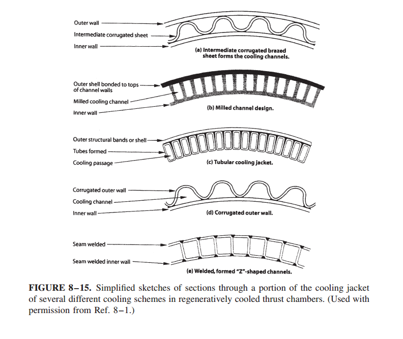
Corrugated Sheet (top): A thin corrugated metal layer sits between inner and outer walls, soldered together in a furnace under external pressure. This design was used extensively in Soviet/Russian engines. It is suitable for mild-to-moderate heat flux zones.
Milled Slot (second): Grooves are machined into a thick copper alloy inner wall. The grooves are filled with wax, then an outer wall is electroplated (typically nickel) to enclose the channels. Finally, the wax is melted out. This design handles the highest heat flux and is standard for throat regions.
Tubular (third): Round tubes are shaped to the chamber contour, then formed into rectangular cross-sections and brazed together with an outer structural shell. This construction was used extensively in US engines like the F-1 and RS-25. It is suitable for intermediate-to-high heat flux.
Corrugated Outer Wall (fourth): This is the simplest and often lightest configuration. It is used where heat transfer is modest, such as the nozzle exit or upstream combustor regions.
Welded Construction (bottom): Made of stainless steel, this design allows higher wall temperatures than brazed constructions. It has been used in nozzles designed and built in Europe.
Channel depth and width vary with axial location. The throat region has the smallest total cross-sectional area, which forces the highest coolant velocity exactly where heat flux peaks. Often, two or three different jacket types are combined in one chamber: milled slots at the throat, tubular or corrugated elsewhere.
Today metal 3D printing technology has now changed that. We are able to design regenerated cooling pipes of almost any shape and bend, which improves both flexibility and performance.
Materials and Failure Modes
Material selection depends on propellants, maximum wall temperature, heat transfer intensity, and duty cycle. Table 8-3 (Sutton, p. 283) lists typical choices:
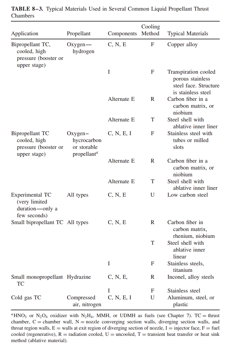
For high-performance regenerative cooling, high thermal conductivity combined with thin walls reduces thermal stress. Copper conducts heat excellently and resists oxidation in fuel-rich atmospheres. However, pure copper lacks high-temperature strength, so inner walls typically use copper alloys with small additions of zirconium, silver, or silicon. These maintain near-copper conductivity while improving strength. This approach is common with LOX/LH₂ engines below mixture ratio 6.0.
Radiation-cooled systems use different materials. Carbon can survive in reducing (fuel-rich) atmospheres up to ~3300 K. Small storable-propellant thrusters use niobium with disilicide coating (up to 1120 K) or rhenium with iridium coating (up to 2300 K). Tungsten, molybdenum, alumina, and tantalum have been tried but face manufacturing difficulties, cracking, hydrogen embrittlement, or oxidation. Hydrazine monopropellant thrusters typically use high-temperature copper-nickel alloys or stainless steel for radiation-cooled walls.
Failure modes are predictable but difficult to prevent entirely. The hot wall bulges on the gas side, and cracks eventually open. During firing, thermal strain at the hot surface exceeds the material’s yield point, causing permanent compressive deformation. After cooldown, residual tension appears. Repeated cycles accumulate plastic strain until cracks form. Eventually these cracks penetrate through the wall, leaking coolant into the chamber. At that point, the thrust chamber fails. Predictably, this will also be a problem for ours, and almost all reusable liquid rocket engines. It determines the number of times they can be safely reused. According to Sutton’s description, useful life is defined as the maximum number of firings before such leakage occurs. Prediction is complex. For small thrusters with many pulses, valve seat fatigue can also limit life, and the storage life of soft components (O-rings, gaskets) may be the actual constraint.
Coolant Selection
Fuel is typically preferred as the coolant for several reasons. First, fuel has higher specific heat capacity than oxidizers—especially hydrogen, which has ~14 kJ/kg·K. Second, fuel leaks are less dangerous than oxidizer leaks; they won’t spontaneously ignite with the structure. Third, preheating the fuel aids vaporization and combustion.
Liquid hydrogen is the ideal regenerative coolant due to its very high heat capacity, low density (which forces high velocity and thus high convection), and lack of coking or thermal decomposition. Hydrocarbons like RP-1 or ethanol also work but risk thermal cracking at hot walls, which deposits carbon that blocks channels and degrades heat transfer.
Design Constraints
The throat region demands the smallest channel spacing and highest coolant velocity. If the coolant reaches saturation temperature, vapor pockets form—heat transfer collapses, and burnthrough follows quickly. The wall must withstand a steep thermal gradient (hot inside, cold outside) without cracking. Narrow channels create high pressure drop, which requires stronger pumps or higher pressure (if using gas-fed).
We will use RPA for this part of calculation.
References:
- Sutton, G.P., & Biblarz, O. (2017). Rocket Propulsion Elements (8th ed.). Wiley. (Ch. 8, pp. 271–311)
- Huzel, D.K., & Huang, D.H. (1992). Modern Engineering for Design of Liquid-Propellant Rocket Engines. AIAA.